- Author Caroline Forman [email protected].
- Public 2023-12-16 11:46.
- Last modified 2025-01-23 09:54.
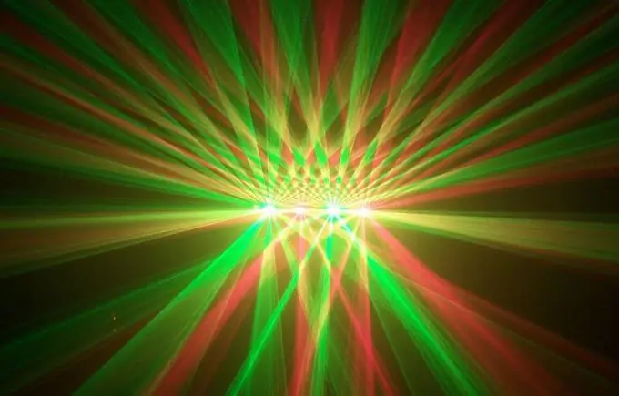
It is impossible to imagine a home disco without color music, and even though this “decoration” of the hall is already outdated, it still has its own charm. It is unlikely that it will be possible to buy lamps, so it makes sense to make an unpretentious design yourself

Necessary
LEDs (12 pieces), 2 resistors per 100 Ohm, 0.5 W, flat 14-wire cable with stranded conductors, LPT connector (male) 25 pins
Instructions
Step 1
First, select a body. You can use a translucent shade, a headlight from a car, or make it yourself. Please note that the screen is opaque, but well translucent by LEDs. Make the distance between the screen and the LEDs at least 1 cm. Leave space for the diodes to output, about 4 cm.
Step 2
Saw a shape out of thin transparent plexiglass to fit the shape of the screen. Mark the position of the LEDs and drill the holes with a 5mm drill. Insert the LEDs into the holes with the lenses outward, lubricating the hole inside with transparent glue. Secure the diodes and bend the cathode of each diode towards the board. Connect the leads on the board with copper wire in 2 groups of 6 leads, soldering.
Step 3
Divide the ribbon cable into cores 2-3 cm longer than the board. Strip one wire from each side of the loop and wind each wire onto the terminals of both resistors. Solder the other lead of the resistors to the wire that connects the cathodes. Strip the remaining wires and thread them onto the LED anodes sticking out of the board.
Gut the ribbon on the other side, strip the wires and solder to the LPT connector.
Step 4
The pins of the plug are numbered from left to right, first the top row, then the bottom, that is, at the top 1-13, and at the bottom 14-25. Pins 18-25 are "ground", solder to any of these pins the two outermost wires of the loop, the same ones that are connected to the cathodes of the diodes through resistors. After that, solder the remaining wires to pins 1-9, 14, 16, 17. This will be the plug.
Step 5
Use Winamp programs, LptLight plugin and GiveIO driver. After that, all that remains is to adjust the LED response levels.


